Category Archives: Electronics

What I look for in a phone

  • 3.5mm Audio Jack
  • Micro SD Slot
  • MP3 & AAC Player
  • 2G & 3G on Bands of my Carrier
  • Bluetooth
  • Wifi
  • Tethering and/or hot spot function
  • Camera – Capable of taking shots of paper/books/white boards
  • Easy to Use and responsive interface (it must go fast regardless of what it looks like)
  • Keyboard
  • Good Call Quality
  • Speakerphone

This allows:

  • Email/SMS
  • Clear calls and group calls with speakerphone
  • Ability to copy documents and white board work
  • Google Maps for navigation
  • Internet for Laptop on the go


Adding Aux Line-in (and USB Power) to an 03 Subaru Impreza Stock Radio

Finished Front Connections to Stereo
I was impressed with Jordan’s simple hack to add an auxilary input to a stock stero head unit and had to try it myself. As my head unit is rather busy on the front panel I routed the input jack into the back of the tray above. I also added a USB charging socket using a 7805 Voltage Regualtor and the data line configuration from Ladyada’s Minty Boost.

WARNING: Obviously opening up your radio and cutting/soldering risks breaking it and will most definitely void your warranty, be prepared to buy a new head unit if it all goes wrong.


Step One: Removing the Head Unit and Cage

On many Subaru’s you have to remove the centre console in order to remove the head unit cage. However on my 03 Impreza Sportswagon all you have to do is pop open the drink holder above the stereo and then gently pop the trim off from around the head unit. Unfortunately I did not figure this out until I had removed my entire centre console! So hopefully the same won’t happen to you.

Step Two: Locating the Radio Lines

Stero Head Unit showing Radio CardI’d recommend reading Jordan’s Post as a reference. You will need to dissasemble your stereo until you can find a point on the circuit board where you can safely cut the radio lines (FM or AM) and then reconnect them through the 3.5mm switching socket. Try and find points where components are soldered in to add your wires, soldering to a track is virtually impossible.

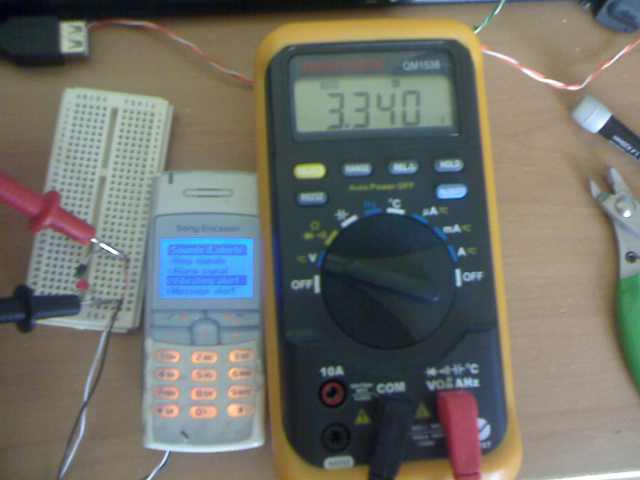
If you can’t locate the lines, you will need to do some diagnostics with a multimeter or give up.


Step Three: Wiring Up the Switching Socket/Jack

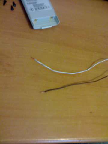
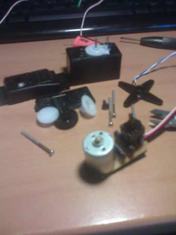
From wikipedia in a 3.5mm stereo jack the tip is left channel, the ring is the right channel and the  Base/last ring is the ground. You will need to look at the data sheet from your socket to determine which pins are which and then solder a wire to each. The pictures show the wiring I used for a socket I bought from Jaycar in Australia.


Step Four: Cut the Radio Left and Right Lines and Solder in the Socket

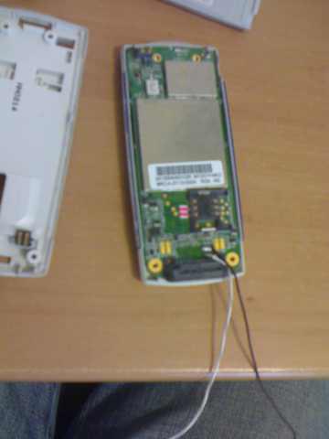
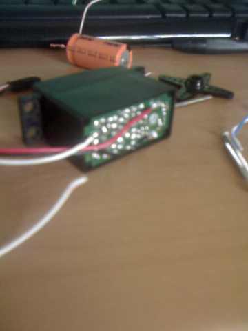
Since my stereo has the radio on a seperate little board inside, I severed the connection between the radio and main amp board for the two FM channels. In retrospect I would have been better finding a section of track to cut as the connection between teh two boards was really strong and I had to use a drill to cut away the connections.

Once the connections were severed I connected the OUT wire connections from the socket to the amplifier side of the lines and the IN wire connections to the Radio side. I soldered the ground wires to the same ground pin on the amplifier side of the stereo (green wire in step five picture).


Step Five: Test Connections with a Multimeter Then Glue

Soldered and GluedSet the multimeter to the beep test (resistance) and check that none of your lines are connected to each other and also that they are connected to the board (probe your connection and next connection along track). Once the connections are checked then you need to glue down the wires so they do not come loose during your next rally.


Step Six: USB Charging Circuit

For the charging circuit I soldered together a USB Socket and the components on the left as per the diagram. Covering the entire circuit in electrical tape to protect it and then soldering it to the VCC and Ground of the stereo. Once again I checked the connections and glued to hold in place.

The data lines attach into the resistor ladder network in order to be held at 2 volts each. This tells many products (Ipods etc – see the minty boost compatability list) to charge and draw half an amp.

Click the diagram for larger image.

NOTE: If you use a USB cable socket as I have you will need to thread the cable through the tray before soldering up the charging circuit.


Step Seven: Mount the connectors

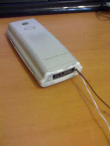
Carefully re-assemble your stereo and route the cables out the back (you may need to bend the casing or drill a hole).

Drill a hole for the 3.5mm socket and mount it into the plastic tray using the screw on the socket and with glue at the back.

If your USB socket is a cable like mine, wrap some electrical tape around the cable as pictures to stop it pulling through and breaking the soldered connections.


Step Eight: Re-install

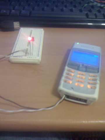
Plug in your stereo before re mounting and turn it on. Be ready to turn it off quickly if there is any smoke, sparks, or bad burning smells, if this happens then something is wired wrong, dis-assemble and re-check everything.

If it powers on without issue check the CD, AM/FM etc are all working as well as your new auxilary line in. Onces it is all working remount the stereo and re-attach the trim etc.

All Done!


Serial Port Power Switch with .NET Control

My friend is part of SOAK (Smart Operational Agriculture Kit) and needed some help putting together a demonstration sprinkler for the project. We ended up with a ‘sprinkler without water’ which can be activated from .NET (we did consider spraying onlookers with water :) ). The main electronics is a serial port controlled switch built using a TIP41C transistor which is activated from a ‘Switch’ class in C# .NET. The SOAK team then wrapped the class in a web service for use with their project.

Switch Features:

  • Uses serial port loopback to automatically detect the com port
  • Low Part Count
  • Can be controlled over the web

.NET switch with sprinkler running

Parts ($45)

1x USB to Serial Port Adapter [$25] (These can be had for $10 if you are running XP, but ones that work with vista are $25 to $50 dollars and I am yet to see one that works with 64bit Vista which is a shame)
1x TIP41C transistor [$1.30]
1x DB9 Plug [$1.00]
1x DB9 Casing [$1.00]
1x Wires [$2] (I’ll let you decide how long you want them, but you will need at least a metre or so.)
1x Battery/Power Source
1x Servo Motor [$10]
1x Roll of electrical tape
1x Sprinkler [$5.00] (I got mine from the local ‘discount’ store)
2x Hours of time [$100?]

Equipment & Download

1x Soldering Iron
1x Wire Cutters
1x Serial Port Switch C# .NET Sample project

Getting Started: The Switch

switch_complete.jpg

Before you  start soldering you might want to check that the circuit is working using a breadboard or just twisting the wires together.

Attach Leads to components

  1. Solder short (5-10cm) lengths of wire to pins 7 and 5 on the DB9 serial port plug. These wires need to fit inside the DB9 casing.
  2. Solder long (35cm) lengths of wire to the second and third pins on the transistor (TIP41C).These will go outside of the DB9 case and connect to our other circuit.

Link the components together

  1. Solder a short piece (1cm) of wire between pins 2 and 3 on the DB9 serial port connector. This connection makes the port a loopback (data sent to the serial port is sent/looped back).
  2. Solder the wire from pin 7 to the first pin on the transistor (TIP41C). This wire carries our on/off signal and connects to the base of the transistor (wire is yellow in diagram).
  3. Solder the wire from pin 5 to the second pin on the transistor. This is the common ground connection this is required for our transitor to activate properly from the signal.

Refer to this diagram

Serial Port Switch Wiring Diagram

Once all the components are soldered together insulate any bare wires with electrical tape and pack the transistor and short wires into the DB9 casing leaving the two long wires protruding through the hole at the back of the casing.Then screw/clip it together depending on your casing.

Testing: The Code

You will need a copy of Visual Studio 2008 (Web Developer is fine) to run the sample project. All you should need to do is plug the serial switch in and run the project and it should find the serial switch port automatically. If not there is probably something wrong with your loopback connection (pins 2 & 3) so you might want to check that. If you are having problems the SerialPortSwitch.cs file is well commented, have a look in there. To operate the project press once to turn it on and once to turn it off.

aspnet_serial_switch.jpg

Bringing it Together: The Sprinkler

Building the sprinkler part was a matter of gluing a servo motor to the sprinkler and then attaching some wire arms to the servo horn to actuate the ‘twacker’ on the sprinkler. The wires were run out the sprinkler water inlet and through the ‘hose’ so that they could not be seen. The pics below should give you an idea of how it was all put together.

Finished: The Video

Dot Net Sprinkler Movie

Improvements:

This switch is not isolated. Meaning that whatever you drive with the switch could feedback into your serial port (eg. damage your computer). Replacing the transistor with an optically isolated component would fix this.

Chris has a nice circuit on his blog that is opt-isolated and can handle low load mains: http://hmmtheresanidea.blogspot.com.au/2008/09/triac-mains-switching.html


Pictures

{gallery}netswitchsprinkler{/gallery}

Minimal parts mobile phone remote button presser

Sample Image

Seeing this article on Hack A Day (and another one where it is connected to an apartment entry buzzer button) got me thinking about a way to make mobile phone activated switch that is simple with as few parts as possible (and cheap). The idea I had was to utilize the existing smarts of a mobile phone coupled with its vibration motor to power a relay or press a button.

Getting Started

WARNING: This is hack will alter your phone and any servo’s permanently and may break them permanently. Perform these modifications entirely at your own risk.

To get started you will need the following bits.

Parts

  • A mobile phone with vibrate (so basically any old cell phone will do).
    • Obviously it also needs to be connected to a cell network.
  • A hobby servo (smaller is better)
  • Some wire (I salvaged mine from an old cat5 cable)
  • Electrical Tape
  • Double sided tape for mounting
  • Solder (For Soldering Iron)

Tools

  • Soldering Iron
  • Needle Nosed pliers
  • Wire cutters
  • Mini Screw Driver Set

Extra Parts experimental tests

  • Two LED’s
  • A large capacitor around 3000uF
  • Bread Board
  • A diode
  • Extra wires
  • Multimeter

Construction

Phone Disassembly

Sample ImageSample Image

  1. Remove the battery from the phone.
  2. Locate the screws holding it together.
  3. Unscrew all the screws (My phone had star shaped security screws, to open I used a flat head screw driver that fitted snugly and it unscrewed no problems.)
  4. Carefully remove bits until you locate the pager motor (see pic below).

Sample Image

Sample Image

The two black and silver things above are pager motors. If you need more reference do a google image search on ‘pager motor’.

Motor Removal and wire attachment

  1. Remove the pager motor taking note of where its connections are (My phone has the connections on the other half of the phone, so the motor connects when the phone is screwed together – your phone may be different).
  2. Fire up your soldering iron.
  3. Strip the ends of two wires, making them around 20cm long.
  4. Now solder the two wires to contacts where the pager motor was connected to the phone.
  5. Next make a hole in the case somewhere for the wires to come out (I used pliers to make a small hole next to the phones connector).

Sample ImageSample ImageSample Image

Phone Reassembly

Now put everything back together how you pulled it apart. Except make sure the two wires you have attached poke neatly through your phones newly made hole.

Sample Image

Servo modification and attachment

Now that the modifications to the phone are done it is time to modify a servo.

  1. Unscrew the servo bottom and remove the motor and gear assembly (If you can access all the connections you don’t have to remove the motor and gear assembly).
  2. De-solder the motor connections from the servo electronics (red and black on my servo – some servo’s are different though so be careful – google your make of servo if unsure).
  3. Solder the connections directly to the motor connections within the servo (Should be two large solder points at the bottom of the servo’s motor).
  4. Re-assemble the servo and its gears.
  5. Now connect the wires from your phone to the servo and insulate with electrical tape.
  6. Test with vibrate mode on the phone. If the servo turns in the wrong direction reverse the connection of your wires between the servo and the phone.

Sample ImageSample ImageSample Image

Phone setup

This will depend on the phone, but what you need to do is set your phone to vibrate mode so that calls activate our newly installed servo.

If you used a newer phone you may be able to set it up to only vibrate for certain callers.

Installation

Now you just need to use some double sided tape to attach the servo to a switch or button so that when the servo turns it will press the button.

Testing

Call your cell phone! The servo motor should turn and activate your device. You may need to re-position your servo for it to work well.

Here is a video of my test:
Mobile Phone Switch Video.mp4

Analysis

What’s Good

  • No variable cost (eg does not cost each time you use it, as you are just pranking the phone). You still need to pay for the account though.
  • Low parts count
  • Easy to implement
  • No need to modify the thing being remote controlled (eg no need to re-wire your apartment buzzer and lose your bond/deposit).

What’s Bad

  • Anyone who has the mobile number can activate it (on simple phone I used).
  • Motor strength struggles and it is only just powerful enough to flip a light switch.
  • Servo motor may be too big for phone and be damaging it (more circuitry could fix this however).

Possible Improvements

  • Use of a phone that lets you customize vibration to specific caller id’s would allow activation by only authorised numbers. My Motorola KRZR lets you do this but I wasn’t willing to sacrifice it.
  • A smaller servo would probably be more easily driven from the phone, which would result in more pressing power.
  • Use the signal to trigger a relay and then drive higher power or other things.
  • I could probably attach this to my kettle Cool!

Expermental Testing

I performed the following tests during development of this hack.

Sample Image

Initially I connected the phone wires to a bread board with two LED’s in opposite polarity to see the signal produced from the pager motor connections. By using two LED’s like this I was also able to ascertain the polarity of the wires.

Sample Image

I also used my multimeter to measure the voltage produced by the pager motor connections. The voltage was 3.3 volts.

Also not pictured I put a 3300uF capacitor into the circuit. This was relatively effective at smoothing the pulses produced by the phone. This meant you got a stable 2v for around 3 seconds which would be good for powering a relay or transistor.

The End

Thanks for watching.

Program a PIC 16F690 with the DIY Kit 150 Programmer

My friend and I bought some PIC16F690 microprocessors. However we didn’t realise that our DIY Kit 150 programmers did not support the 16F690. Luckily a new firmware and software update is available (Beta) which supports the 16F690. Read on to see the process I used to upgrade my programmer and program my 16F690.

You will need the following:

  • DIY Kit 150 programmer
  • DIY Kit 150 ICSP Cable/Break Out
  • Bread board (the electronics kind)
  • 1x PIC 16F628A
  • The version of Micropro that works with your KIT150 programmer
  • Beta Version 26 MicroPro and firmware pack
    • This is lurking around on the web, I downloaded it here. Distrubution of the beta was stopped because some company in the US was ripping off kitsrus.
  • Test program/hex file for the 690

The DIY Kit 150 programmer has a firmware chip (a pic16f628a) which can only be used with the corresponding verison of Micro Pro. In order to upgrade to the new version we must program and install a new firmware chip to use with the new version of Micro Pro.

Upgrading your programmer:

  1. First we have to program a new firmware chip for your programmer. So ensure you have your current version of MicroPro installed and working.
  2. Next unzip the Beta Version 26 MicroPro and firmware pack, and install it. It should install into a different directory (mine was c:diypgmrt) from your current/old version of Micro Pro.
  3. Now plug in your programmer and fire up your old version of Micro Pro, insert the PIC16F628A chip into the programmer.
  4. Load k150.HEX from the folder of the new Micro Pro installation. This is the new firmware.
  5. Program and then verify the 16f628a with the new firmware.
  6. Remove the newly programmed 16f628a and label it ‘V26’.
  7. Completely power down and disconnect your programmer and close the Micro Pro application.
  8. Remove the existing 16f628a from your programmer (the one that is part of the programmer components) and label it with your programmers current version number.
  9. Now install the newly programmed 16f628a with the V26 Firmware in place of the one we just removed.
  10. Now open the new version of Micro Pro and check that your programmer works. Make sure you keep the old 16f628a with your old firmware as if this does not work you will need to swap it back to get your programmer working again.

Programming your 16f690 via ICSP:

  1. Place your 16F690 into the bread board so that each pin is on a seperate track.
  2. Plug in your ICSP break out cable and plug each wire into the track of the corresponding pin as per the diagram below:
    • Note: ignore the colours in Micro Pro they do not match properly.
    • Note: the LOW pin is not used.
  3. Load the NEW Version Micro Pro and select ’16F690-I’ from the chip list.
  4. Load your test .hex program (must be for 16f690)
  5. Program and then verify your 16f690!


DIY USB Travel Charger

A couple of days ago engadget featured this airline USB travel charger that charges your device really slowly from the aircraft audio jack. I wanted something cheaper better so i could use my ipod, phone and camera during my international flight. So I made this AA battery powered USB charger form parts I had lying around.


What you will need:

  • Short USB Extension lead
  • 4xAA Battery Holder with On/Off Switch (cost about a dollar from Jaycar Electronics )
  • 5V Regulator (L7805 – Rated to 1 Amp)
  • Soldering Iron and Solder
  • Wire cutters
  • A multimeter
  • A glue gun OR glue OR blue tack OR gum…
  • 20 Minutes to put it together

So construction is pretty simple:

NOTE: Check your polarity (+ve’s and -ve’s) and voltages with the multimeter after each step.

UPDATE NOTE (21/10/2007): Originally I used a voltage regulator however the 5-6v from the battery pack was not enough for it to sustaion 5v so I had to remove it to get it to charge properly. The max output voltage with 4 AA batteries is 6V so it is unlikely to hurt any usb things.

  1. Chop the usb extension cable about 15cm from the socket end.
  2. Expose the 4 wires in the usb cable, and identify the two which are for power (They should be thicker, mine were red for +ve and black for -ve).
  3. Make or enlarge a hole in your battery holder so that the usb extension cord fits in tightly.
  4. Find a place in your battery holder to fit the L7805 and solder the battery holder leads to it.
  5. Feed the usb cord into the hole we made in the battery holder. so that the 4 wires are dangling on the inside and only full shielded usb cord is on the outside of the battery holder.
  6. Solder the +ve and -ve from the usb cable to the L7805 the battery holder to the +ve and the -ve of the usb cable.
  7. Tuck the L7805 and any wires neatly into the inside of the battery holder.
  8. Check the polarity and voltage on the usb socket using the multimeter.
  9. Glue any parts that may come lose in on the inside if the battery holder.
  10. All Done.

Happy Charging!

NOTE: This setup will not charge all things (it works with my ipod, but not my motorola phone). This is because in the usb spec devices are supposed to contact the host (pc or usb hub) and request high power mode. As this setup has nothing to request high power mode from, the device will never try to charge (as it will assume high power mode is unavailable).
The Minty Boost Kit has the electronics required for most usb devices to work.